
Institute of Circuit Technology Northern Seminar,
Hartlepool, 6th November 2012
A new venue for the Institute of Circuit Technology's Northern Seminar: Hartlepool's Historic Quay, with the three masts of Britain's oldest warship afloat, HMS Trincomalee, a classic British frigate dating from 1817, dominating the skyline.
 ICT Chairman Professor Martin Goosey welcomed over 60 delegates to the Northern Seminar, now an established annual event which continues to increase in popularity year-on-year, and gave an update on ICT activities and member benefits with special mention of the recently upgraded website and the quarterly Journal. The ASPIS FP7 project, now entering its third year, was contributing greatly to the understanding of failure mechanisms and the development of process improvements in ENIG technology.
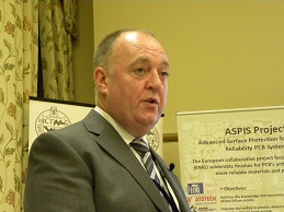
Professor Goosey introduced a well-chosen programme of four papers from eminent speakers, the first of whom was Martin Cotton, Director of Technology Europe for SCI-Sanmina.
 Renowned for his stylish and provocative presentations, Cotton developed a very convincing argument around the cost benefits of intelligent panelisation, with apologies to the laminators present for encouraging their customers to use less material. And in the context of a multinational EMS provider employing 22.000 people and turning over $6billion annually, he nominated panelisation as the number one parameter for cost avoidance and demonstrated with many actual examples how a small cost saving per unit could add up to hundreds of thousands of dollars.
In order of precedence, the PCB designer usually occupied a position downstream of the mechanical designer. Instead of having the opportunity to optimise panel layout for best utilisation of material and most efficient manufacture, he was too often constrained by a fait-accompli mechanical design, and had to fit his PCB into metal and plastic components and enclosures whose dimensions had already been committed. Mechanical issues had a huge effect on PCB cost; therefore it was important to design the PCB first, and then design the enclosure around it. It was essential for design and manufacturing to work together with marketing to carry out proper value analysis at the earliest stages of the design cycle, and certainly before the mechanical design was frozen.
"If you think the PCB designer has a challenging job, put yourself in the position of a shoe-maker panelising a hide for cost-effective shoe production."
A particular area of unnecessary waste in PCB design was the incorporation of supporting rails for transporting circuits through assembly equipment. By straightforward rationalisation of panel sizes, Cotton demonstrated that rails could be eliminated and that the investment cost of re-usable carriers could be recovered very rapidly through material savings.
Designers were notorious for being stubbornly resistant to change. How to overcome that resistance? "Let their bosses know how much money can be saved!"
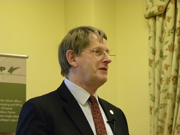
 A resolute supporter of ICT events besides his duties as Chairman of the EIPC, Alun Morgan, Director of OEM Marketing for Isola's European operation, gave an elegant and articulate presentation on high-frequency laminates and thermal reliability, beginning by discussing the causes of signal losses, where they occurred and ways in which the laminate manufacturer could help to reduce them. He explained the concept of the skin effect: the tendency of a high frequency signal to distribute itself so that the current was carried near the surface of the conductor, the higher the frequency the greater the effect, the closer to the surface, and how this contributed to conduction losses in copper foil, exacerbated by the roughness of the bonding treatment. Consequently, the choice of copper foil treatment could be critical when specifying laminate. "Low-profile" (LP) foil had a surface roughness of less than 5 microns and even lower-profile materials were in development. "Don't forget the oxide!" was a reminder to PCB fabricators that their own in-process bonding treatments could have significant effect on impedance, and that proprietary chemistries from alternative suppliers did not necessarily give similar results.
Considering the dielectric losses associated with the glass and resin components of laminate, Morgan demonstrated how heat was generated, and hence energy consumed, by applying an alternating signal to a polarisable material. The action of a microwave oven was a familiar example. Because the dielectric constants of glass and resin were different, the effect on impedance and signal integrity varied according to whether a conductor was passing over microscopic resin-rich or glass-rich areas of the laminate, according to the weave of the fabric. The effect was much reduced by using fabrics where the yarns and filaments were more uniformly distributed.
Standard FR4 laminate typically had a bulk loss factor of 0.015, whereas non-polarisable materials like PTFE and certain ceramics could be as low as 0.002. New-generation laminates were becoming available with loss factors approaching 0.003 without the use of PTFE or ceramic, which offered cost savings and easier processing. It was significant that water had a loss factor of 0.06, so moisture absorption in laminates could dramatically increase its loss characteristics. It was now practicable to manufacture laminates with resin systems that exhibited very low moisture absorption, good thermal stability and low thermal expansion, which showed a favourable combination of low loss and high thermal reliability.
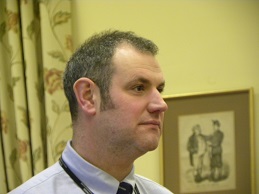
 Alun Morgan having described characteristics of and developments in rigid laminates, it was appropriate that the following presentation should discuss corresponding aspects relating to flexible materials. Roger Jamieson, Account Manager for Circuit and Packaging Materials with DuPont, gave an authoritative review of polyimide materials for flexible circuit applications. Flexible laminates could be classified into two distinct groups: adhesive-based and adhesiveless. Adhesive-based materials relied on a layer of acrylic or epoxy resin to bond the copper foil to the polyimide core, whereas in adhesiveless materials, the bond was directly between the foil and the core, either by sputtering copper onto polyimide film or by casting polyimide resin on to copper foil.
Foil for flexible applications could either be electrodeposited (ED), as used in the manufacture of rigid laminates, or rolled-annealed (RA), which was generally preferred because of its better flex-fatigue properties and high-temperature performance. Jamieson presented a chart of recommendations and guidelines for flexible materials to suit a range of particular applications.
Although it exhibited many desirable properties, a shortcoming of polyimide film was its natural tendency to absorb moisture.
There had been some interesting recent developments in flexible materials for high frequency applications, where the polyimide film was sandwiched between two layers of fluoropolymer, resulting in dielectric constant about 2.4 which enabled controlled impedance circuits to be made with wider conductors and thinner cores.
 Mention of controlled impedance flexible circuits led logically into the final presentation, entitled: "Impedance control considerations for flex and flex-rigid designs" from Neil Chamberlain, Signal Integrity Product manager with Polar Instruments. Accurate modelling was vitally important for effective impedance calculation, and there had been significant advances in numerical field solving techniques. 2D field solvers could now be successfully applied to the mixed dielectrics found in flex-rigid constructions.
After declaring: "All models are wrong, but some are useful!" Chamberlain discussed recent developments that enabled the modelling of transmission lines on flexible circuits with meshed or crosshatched ground return planes, which had previously presented some difficult challenges. He remarked that solder masks and coverlays could have large effects on impedance, and needed to be taken into account in the modelling process. The tendency of polyimide to absorb moisture introduced further complication into the modelling process.
Regarding the local effects of glass fabric reinforcement in rigid materials, as Alun Morgan, had discussed, he remarked that some designers even resorted to routing their transmission lines at a 12½º angle to the weave in order to even-out microimpedance variations. Again, with reference to the effects of copper surface roughness, where historically it was normal practice to specify core layers for critical dielectric spaces, there was now a trend to design such spacings between etched layers to avoid the treated sides of the copper.
Customers were developing an awareness of loss as well as impedance, and factors such as trace geometry, via dimensions, material characteristics and conductor quality were of increasing significance. Chamberlain predicted that laminate selection would become more and more important.
 ICT Technical Director Bill Wilkie brought proceedings to a close and extended his thanks to Falcon Group and Merlin-Flexability for supporting an excellent event.
Pete Starkey
PCB007
November 2012
